Atv Kill Switch Wiring Diagram

Vt Commodore Ignition Wiring Diagram, Complete Wiring Diagrams For Holden Commodore VT, VX, VY, VZ, VE, VF, 5.36 MB, 03:54, 32,796, John Amahle, 2018-08-01T19:37:41.000000Z, 19, Vt Commodore Ignition Wiring Diagram, to-ja-to-ty-to-my-to-nasz-swiat.blogspot.com, 1272 x 1800, jpeg, bcm pcm 12j swiat nasz, 20, vt-commodore-ignition-wiring-diagram, Anime Arts
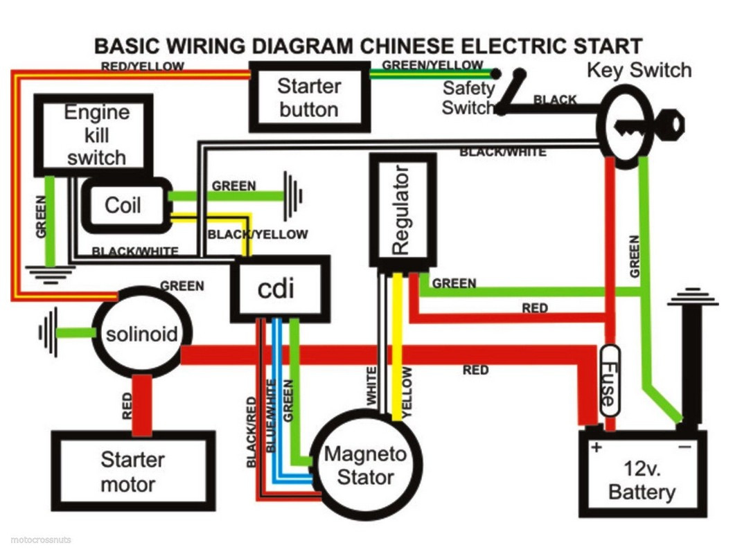
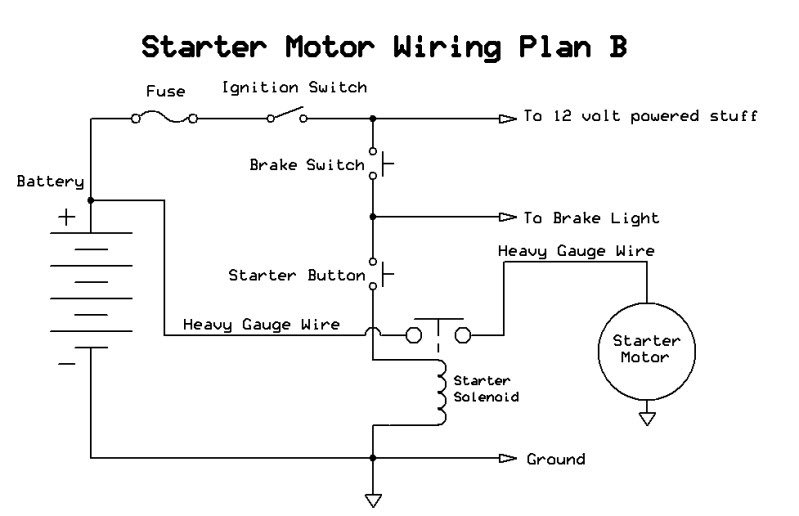
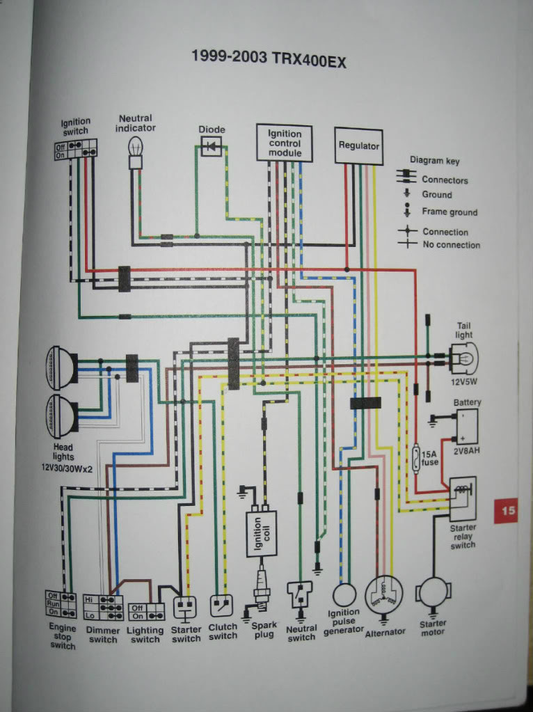
In the above diagram, the kill switch is set to run which provides the ecu with a ground supply. Power, therefore, flows from the stator via the rectifier which provides power for both the ecu and the coil. The ecu receives an input signal from the pickup which as you know is triggered by the rotating crankshaft. Eton 50 cc atv wiring diagram.
Eton 50cc 40e rxl. Eton 50cc atv kill switch wiring diagram. 9 pics about eton 50cc atv kill switch wiring diagram : Joined may 17, 2014. #2 · aug 5, 2019. It does not matter which red/blk is connected to which red/blk on the pigtail. Shop owner and mechanic with over 50 years experience. Full electric wiring harness loom cdi coil for gy6 cc cc atv. Wiring diagrams for 88, , and cc engine · wiring instruction for 70cc, cc and cc with yellow plug 50cc cc moped gy6 wire diagram motorcycle atv bike audio fm radio mp3 aux stereo system manual.
tao tao 110 key switch and kill switch dont work - ATVConnection.com ATV Enthusiast Community

Ignition Kill Switch Wiring | schematic and wiring diagram | Kill switch, Motorcycle wiring

remote kill switch, now mini atv wont work! help! - ATVConnection.com ATV Enthusiast Community

50CC - 125CC TAOTAO KAZUMA ATV DUAL REMOTE CONTROL KILL START SWITCH ROKETA SUNL - Buy Online in

Eton 50cc Atv Kill Switch Wiring Diagram

Image result for wiring diagram for taotao 110cc atv | Atv, 50cc atv, Diagram

Honda Trx250tm Killswitch Wiring Diagram

Cdi Wiring Diagram Elegant 4 Wire Ignition Switch Diagram Atv New in 2020 | Kill switch

43 Ignition Kill Switch Wiring Diagram - Wiring Niche Ideas

wiring diagram for chinese 110cc atv engine wiring diagram images in 2020 | Xs650, Electrical
