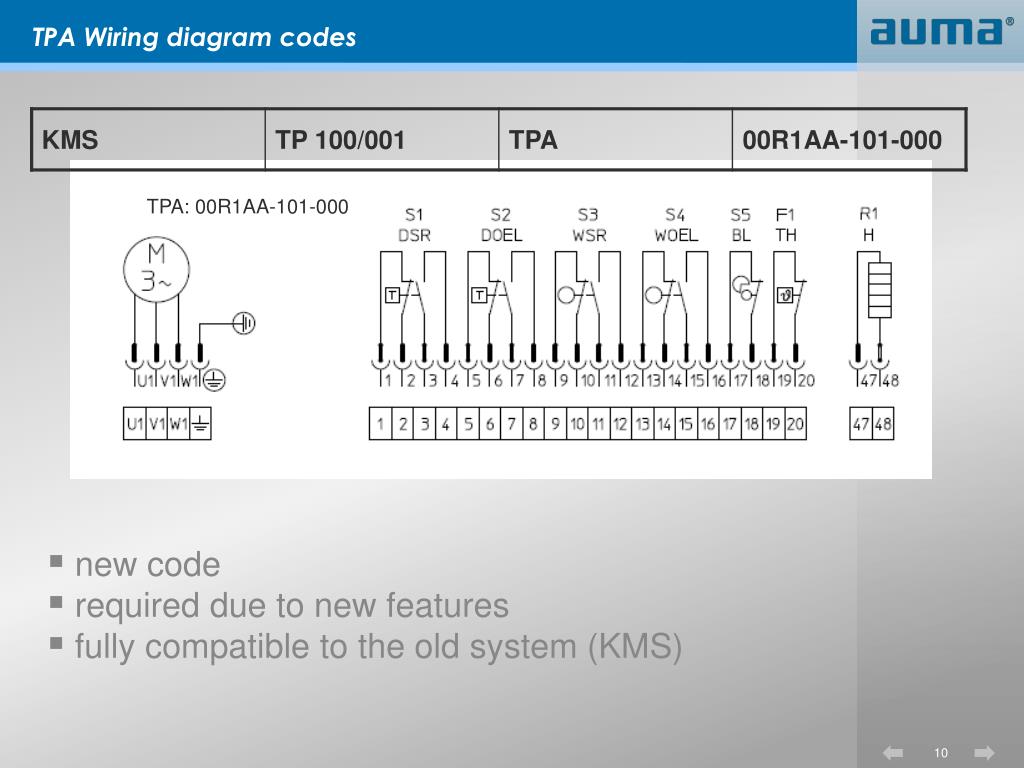
Auma Sa 07.2 F10 Wiring Diagram

Vt Commodore Ignition Wiring Diagram, Complete Wiring Diagrams For Holden Commodore VT, VX, VY, VZ, VE, VF, 5.36 MB, 03:54, 32,796, John Amahle, 2018-08-01T19:37:41.000000Z, 19, Vt Commodore Ignition Wiring Diagram, to-ja-to-ty-to-my-to-nasz-swiat.blogspot.com, 1272 x 1800, jpeg, bcm pcm 12j swiat nasz, 20, vt-commodore-ignition-wiring-diagram, Anime Arts
En iso 5210 (din3210) f07 f10 (g0) f07 f10 (g0) f10 (g0) f14 (g1/2) f14 (g1/2) f16 (g3) a1 40 40 50 67 67 80. With auma plug/socket connector b. How to look good in school uniform when your fat; Can you buy chewing tobacco in cabo san lucas
Globe valves, gate valves, butterfly valves, and ball valves. Other applications require explicit (written) confirmation by the manufacturer. 2 f10 схема подключения. Схема подключения открывается во всплывающем. Eim actuator wiring diagram sample wiring collection. Mounting positions actuator controls on actuator1) mounting position a please consider possible space constraints on site when selecting the mounting position. Mounting positions may easily be changed at a later date. Output speeds of 4 to 180 rpm at 50 hz supply. Motor without terminal box, internal.
Wiring Diagram For Actuator

Auma Valve Wiring Diagram - Wiring Diagram Schema

Auma Actuator Wiring Diagrams - Wiring Diagram

Auma Actuator Wiring Diagrams - Wiring Diagram

Auma Mov Wiring Diagram - Wiring Diagram and Schematic
Auma Valve Actuator Wiring Diagram - Wiring Diagram

Auma sa 07.2-f10/vd0063-4/30b/AC 01.2 ELETTR. drehantrieb, metti attacco-used - | eBay

Auma Actuator Ac 01 2 Wiring Diagram - Wiring Diagram

Auma Usa Wiring Diagram - Wiring Diagram

Auma Mov Wiring Diagram - Style Guru: Fashion, Glitz, Glamour, Style unplugged
